Next Step in the Ledger
From Chamber Air to Verified Evidence
Discover how thermal mapping results dictate permanent sensor placement, buffered probe configuration, and alarm verification thresholds.
A temperature-controlled warehouse succeeds or fails first as a physical barrier against ambient heat and water vapor, and second as an air-distribution machine. Even oversized compressor capacity cannot produce uniform storage conditions if warm humid air infiltrates through poorly sealed floor joints or dock vestibules, icing up evaporator coils and creating steep thermal gradients across racking aisles.
For operations managers, understanding the interaction between building envelope, refrigeration plant, and pallet stowage discipline clarifies why two chambers set to the same controller reading can deliver markedly different product stability.
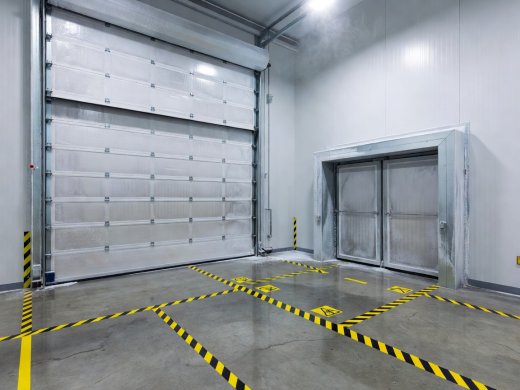
Warm outside air holds significantly more moisture than chilled or frozen indoor air. This partial-pressure differential drives water vapor continuously toward the cold side of the wall. In a refrigerated facility, the continuous vapor retarder must be positioned on the warm exterior face of the insulated envelope— typically formed from polyisocyanurate (PIR) or polyurethane (PUR) sandwich panels with sealed tongue-and-groove joints.
When a vapor seal is punctured by unsealed conduit penetrations or forklift impact, moisture migrates into the insulation core, condenses, and freezes. Ice conducts heat roughly four times faster than liquid water and nearly a hundred times faster than still air, progressively destroying the panel’s thermal resistance.
In chambers operating continuously below 0 °C, heat is drawn steadily out of the earth beneath the concrete floor slab. Without intervention, the 0 °C isotherm gradually descends into the subsoil, freezing ground moisture into ice lenses that expand and heave floor slabs upward, tilting high-bay racking out of plumb. Facilities prevent frost heave by installing an insulated sub-floor over an actively warmed or ventilated under-slab layer—using glycol heating loops, low-wattage electric trace cables, or cross-ventilated air ducts kept strictly above freezing.
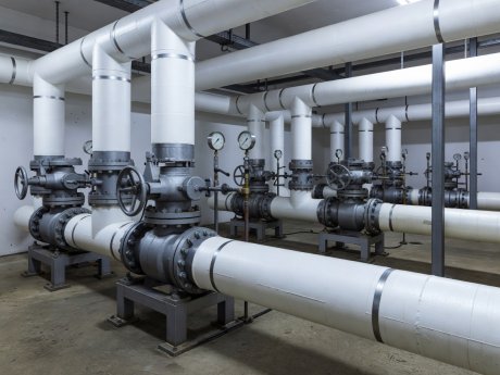
Industrial cold stores rely on central mechanical plant—commonly pumped overfeed ammonia (R717), transcritical CO₂ (R744), or ammonia/CO₂ cascade architectures, alongside secondary glycol loops for medium-temperature chill rooms. Regardless of the refrigerant inside the coils, the product only experiences the air moved across it by the evaporator fans.
Airflow always follows the path of least resistance. If pallets are pushed flush against exterior walls, stacked into the ceiling plenum above the maximum load line, or jammed tightly together without flue spaces, conditioned air bypasses the stock and returns directly to the suction intake. Maintaining clear perimeter standoffs, ceiling clearance for air throw, and clean under-pallet channels ensures that heat infiltrating through walls is swept away before reaching the load.
A holding chamber is engineered to maintain products that have already reached their target core temperature. Pulling down warm production batches requires dedicated blast cells or tunnels equipped with high-velocity fans and high-capacity coil surfaces designed to move products rapidly through the zone of maximum ice-crystal formation without warming adjacent stored inventory.
World Health Organization (WHO) technical supplements on temperature mapping and USP <1079> good storage practices emphasize that fixed building management sensors alone cannot prove uniformity across a three-dimensional room. Formal thermal mapping deploys a calibrated grid of data loggers across upper, middle, and lower racking tiers—first in an empty state to verify baseline mechanical performance, and subsequently under representative loading across warm and cold seasons.
Mapping exercises consistently identify two vulnerable zones: the top racking level beneath the roof deck (subject to solar gain and stratification) and the floor area immediately inside dock doors. Controlling the dock interface requires desiccated air curtains, rapid-roll doors interlocked with outer bay doors, and vertical-storing dock levelers that allow trailer doors to be opened only after the vehicle is sealed inside the building envelope.
Discover how thermal mapping results dictate permanent sensor placement, buffered probe configuration, and alarm verification thresholds.
See how trailer pre-cooling, airflow chutes, and insulated bulkheads preserve warehouse conditions once pallets cross the dock plate.
Cookies on this site Essential cookies keep this site working. Optional ones help us see what is useful. You can change your choice at any time. More about cookies